
So, here’s Terrific Tuesday #002.
Our last Terrific Tuesday was caused by my brain not functioning well in isolation, as I forgot what day bin day was. This time, it’s because it was Easter Monday yesterday in the UK, and I decided to enjoy the public holiday we have here, even though I was only at home (#stayathome).
On this Terrific Tuesday though, I have decided to REMEMBER a very old blog series I created WAY back! I had a laptop stolen all the way back in February 2012. I had some current blog posts stored on it and I lost that data. I promised a Part 4 of the blog series, Measuring Areas (AutoCAD) after the theft, but for whatever reason, I forgot to post the last part of the series. With the recent website rebrand, I found the blogs for Parts 1-3, and I just wanted to redress my tardiness with Part 4.
Firstly, please note that I will be using AutoCAD 2021 for the final part, and yes I know, it was all the way back with AutoCAD 2012 (yes, 2012) that I started this series, so I can only apologise profusely for the over EIGHT years of waiting!
Secondly, I did lose the datasets for the blog with the laptop theft, so I have recreated a similar dataset, so the screenshots will look a little different to the first three parts.
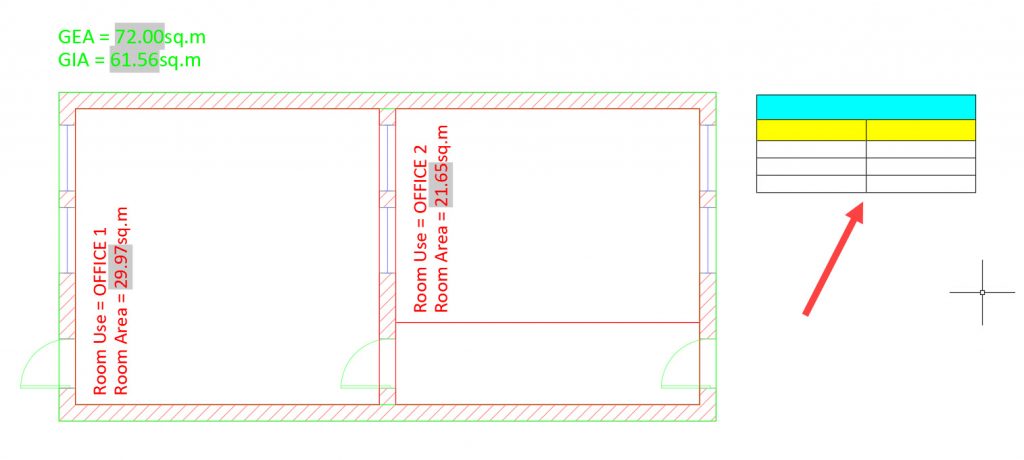
In this tip, I want to show you how to take your area data from your drawing and put it into an AutoCAD table in the Model tab. I have already created the layers, XREFs, and polylines for the gross areas and the room areas and added the appropriate text fields to show the various areas in multiline text (MTEXT).
I have created an AutoCAD table style to suit my needs, rather than bore you with creating a table style in this blog. It is called FM AREAS.
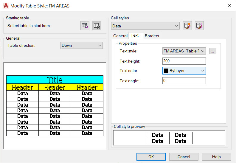
I have set up the style to suit the units I am using in the Model tab (metric millimetres) just for now. Obviously, you could set this up in any which way, depending on your units you are using. I have set it as the current table style.

Then, using the Insert Table command, using the FM AREAS table style, I have set up the table settings as shown below, using a specific table insertion point (top right in dialog box): –
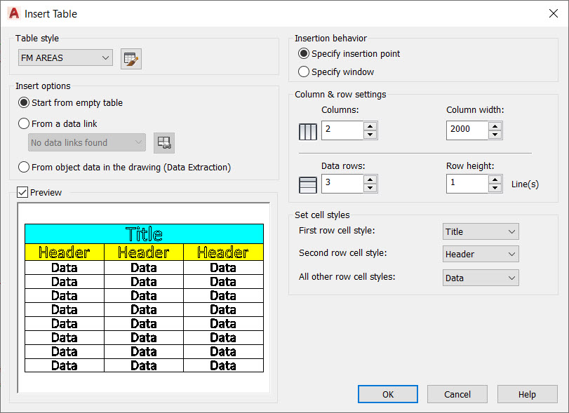
I have clicked on OK in the dialog box and then placed my new empty table to the right of the FM floor plan as shown: –
Just make sure you hit ESC (Escape key) a few times to deselect the table after placement.
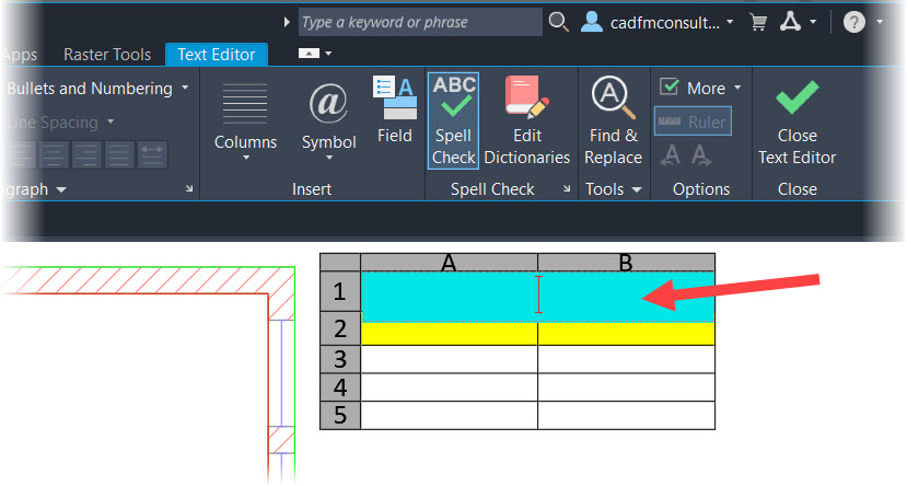
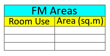
The table will be called FM Areas so we need to add that to the Title cell of the new table. Double click in the TOP cell of the table to activate the text editor. You will see that I have given the Title cell a cyan background in the table style.
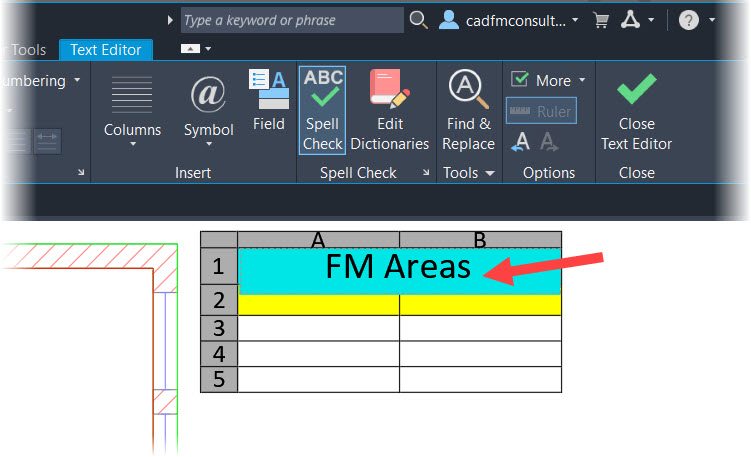
Type in ‘FM Areas’ and then simply click away from the table or click the green tick in the contextual Text Editor ribbon tab. You will see the table update accordingly. That’s the title of the table sorted.
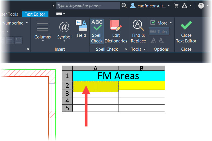
We now need to name the Header cells of the table. I have given these a yellow background in the table style. Double-click in the LEFT Header cell and the text editor will kick in again.
Set the left header cell to use the text ‘Room Use’ and then simply TAB across to the RIGHT header cell and set the text to ‘Area (sq.m)’. You can also use the right arrow key instead of TAB. Click away from the table when you are done typing and you will see a table that should look a bit like this: –
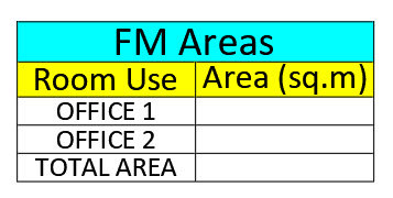
We now need to put our Room Use values into the LEFT data column. These will just be text elements in each cell that we type in, and they will replicate the room use text elements in our multiline text for each room in the drawing. In the THIRD data cell in this column, type in ‘TOTAL AREA’. You will see why later.
Again, it’s a double-click in each cell to activate the cell. I have done these in advance, and your table should now look like it does below when you click away from it in the Model tab. Remember to use the arrow and tab keys to navigate your table when adding text into the cells.
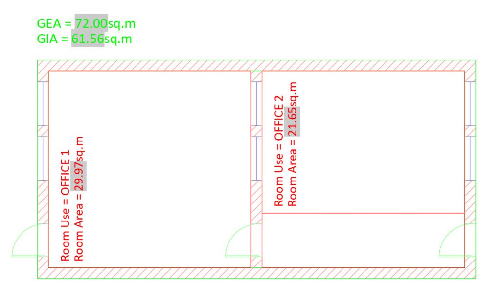
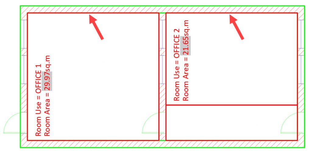
We now need to add FIELD data to each of the area cells in the RIGHT column that correspond to each room polyline in the drawing. Make sure that your layers for your room polylines are visible in the Model tab (check that they are ON and THAWED). I have used the Lineweight function in AutoCAD to highlight these polylines for you.
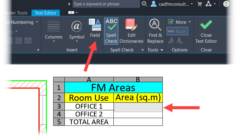
Double-click on the TOP RIGHT area cell in the table, that corresponds to Room Use OFFICE 1 and then select the Field command in the contextual Text Editor on the AutoCAD ribbon.
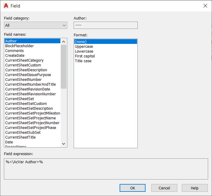
When you execute the Field command, a weird dialog box will appear. Don’t panic. It simply shows ALL the fields available in your drawing, and we just need to refine that in the dialog box by selecting the appropriate settings.
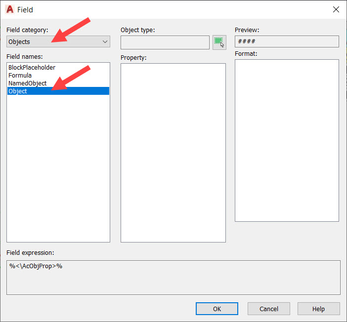
In the Field category dropdown (top left), select Objects. In the Field names dropdown, select Object.
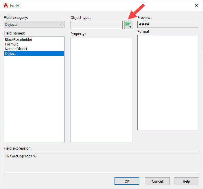
Then, next to Object type, click on the Select object icon (shown below).
In the drawing, in the Model tab, use the pickbox to click on the polyline (in this case), that represents the Room Use OFFICE 1. Your Field dialog box will change to show the following field data for that particular polyline.
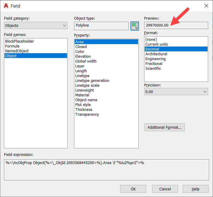
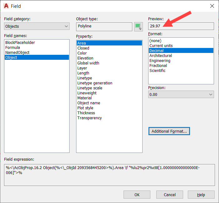
You can now see that the Field dialog box displays the field data for your chosen room area polyline in the Property area of the dialog box. In fact, it defaults to Area as it is at the top of the property list for your polyline too. You can see that the ACTUAL value for the area (29970000.00) is shown in the Preview field (top right) which is shown in square millimetres, as that is the incumbent unit setting for the drawing.
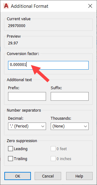
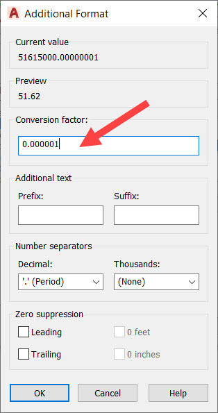
Our column in our table needs to display this value in square metres (sq.m) so we need to click on the Additional Format button. This opens a new dialog box and you need to edit the Conversion factor field to the value shown by the arrow.
Click on OK in the Additional Format dialog box and you’ll be taken back to the Field dialog box. You can now see the preview reads in square metres, as shown below by the arrow.
Click on OK in the Field dialog box, and you will be taken back to your drawing, with your cell still current in the table. It now displays your square metre area value.
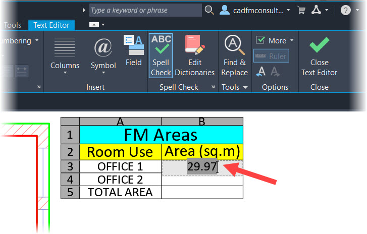
Click away from the table and your field value is now in the cell, with a grey background masking to emphasize that it is a field value from an object, and not just a text element.
You then need to repeat the above process with the next cell down for Room Use OFFICE 2, so that your table then looks like this: –
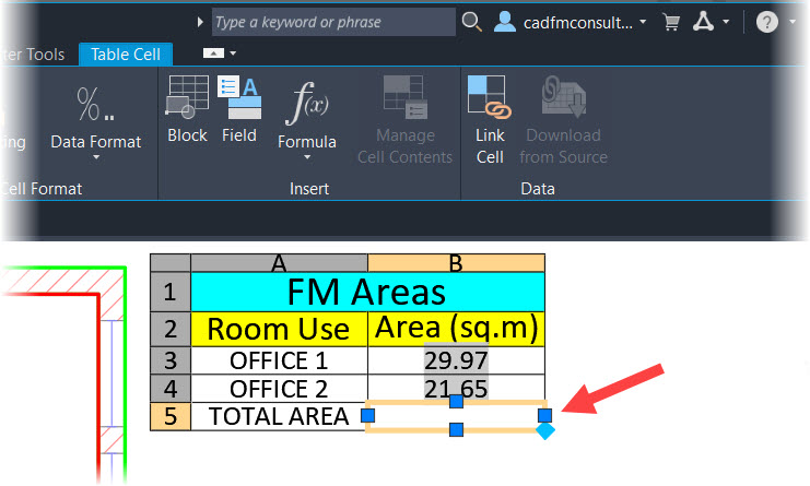
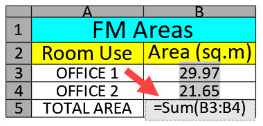
AutoCAD’s tables also give you some spreadsheet functionality, similar to MS Excel. You can add up your room areas to get a total area. Click ONCE in the TOTAL AREA cell (currently empty – bottom right). It highlights differently and you now have a contextual Table Cell tab on the ribbon.
Click on the Formula dropdown in the Insert panel on the ribbon.
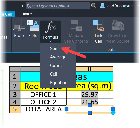
Select Sum and then click-drag-click a selection window over the two area cells with values in them.
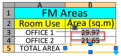
On the second click of the window, the sum formula will appear in the total area cell in the right-hand column.
Click away from the table in the drawing area or click on the green tick in the ribbon. You will then get a weird large value appear in the cell, or a bunch of hashtags (########), indicating the cell is too small to display the summed value.
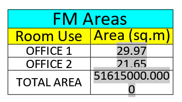
In my case the value is way too large (it is the square millimetres value), and we need to change it to square metres. Click once on the cell to highlight it once more. The Table Cell contextual tab on the ribbon should appear again.
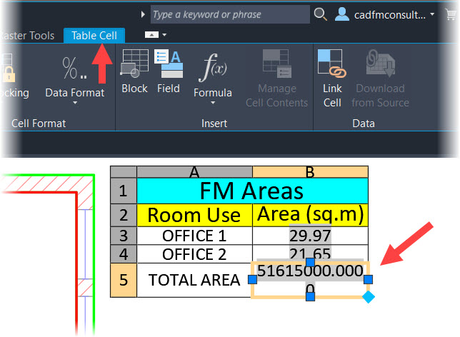
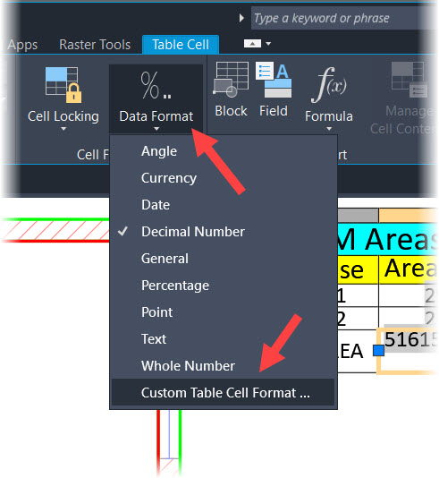
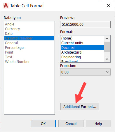
Select Custom Table Cell Format… in the Data Format dropdown. You will find it in the Cell Format panel on the ribbon.
Make sure your Precision is set to 0.00, and then click on Additional Format in the Table Cell Format dialog box. Look familiar yet?
Make sure the settings are as follows: –
Click on OK and then click on OK in the Table Cell Format dialog box. Your table should now look like this: –
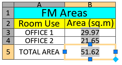
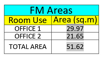
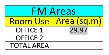
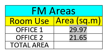
Hit the Escape (Esc) key a few times and you now have a FM Areas table, albeit a simple one, like below.

You can now apply this in any of your drawings where you need to calculate areas. It doesn’t have to be rooms. It could be areas of metal plates with holes in, or usage of a landscaped area perhaps.
So, there you have it. The FINAL part of this blog series about areas in AutoCAD. It only took me eight years to write, but we got there, right? 😉
You can find the other three parts here: –
These strange times we find ourselves in are allowing us to finally finish things we have started. My suggestion is to find all those ‘little’ jobs you always wanted to finish. Then, when lockdowns are lifted, we have a clean slate to start from!
On a more personal note. Hang on in there, stay safe, and most of all, be kind to one another. #bekind
It’s Terrific Tuesday.
Be terrific to others, and yourselves too. 😉
SCB.
PS – You can find my new CAD & BIM: Workflow For Areas In FM course in the LinkedIn Learning library here. Check it out and find out more about using areas not just in AutoCAD, but also in a Facilities Management (FM) workflow too.
PPS – You can also find out more about AutoCAD 2021 in my new AutoCAD 2021 Essential Training course in the LinkedIn Learning library here.