
Level: REGULAR USER/INTERMEDIATE
OK, as promised (!), here we are for Part 3 of Measuring Areas in AutoCAD 2012.
In Part 2, I showed you how to calculate areas using the AREA command. What I am going to show you in Part 3 is how to use AutoCAD FIELDS to display those area values on your drawing as exact units of measurement. Now, I am based in the UK, so I will be calculating my room areas in square metres. However, those of you who still use imperial measurement (my American friends, for example), you can still do this with square feet if required.
Now, we still have our room and floor polylines displayed on our drawing. These drawing entities have information associated with them that can be displayed using FIELDS. This is the xData I mentioned in Part 2. The best bit about FIELDS is that when a polyline is edited and the area changes so does the area value in the displayed FIELD.
Section 1 – Displaying Floor Area with FIELDS
So, let’s do the easy one first. Our floor area. The drawing is very simple and we have one rectangular polyline (in green) representing our floor area.
Utilising the AutoCAD ISOLATE command from Part 2, we will isolate the floor area so that nothing else gets in the way. We can easily move the text we create later. So, just select the green floor polyline and right click and select Isolate. Fig.1 shows the isolated polyline.

Fig.1 – The isolated floor polyline
We can now use the Multiline Text command (MTEXT) to place some text within the polyline. Make sure you have a suitable text style (I tend to use Calibri or Verdana as my font) and make sure the text is the right height for use in the Model tab. In this example, I have used a text style called LABELS and given it a fixed text height of 150mm in the text style. See Fig.2 below.

Fig.2 – The Text Style dialog box
We will put the text directly in to the design space (Model tab) as they are purely labels and do not require any annotation scaling. If you know how to use annotative scaling and wish to use it, please do so. I will be writing a blog on annotative scaling in the future so don’t worry if you haven’t got a clue what I am talking about!
Using MTEXT with your chosen text style (in my case, LABELS), place your text area in the centre of the polyline area as shown in Fig.3. I have set my current layer to the same layer as the floor polyline, FLOORAREAS.

Fig.3 – Placing MTEXT in the centre of the floor area polyline
Type the following in the Multiline Text Editor once you have placed your text area:
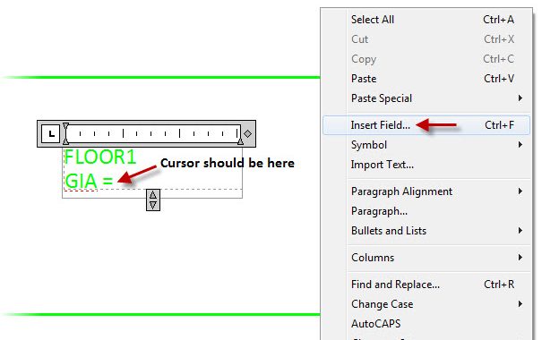
FLOOR 1
GIA =
(GIA is an abbreviation for Gross Internal Area).
Then with the text cursor just after the EQUALS symbol, right click and select Insert Field as shown in Fig.4 below.

Fig.4 – Using Insert Field on the right click shortcut menu
The FIELD dialog box will appear. In the FIELD CATEGORY pulldown (top left), select OBJECTS. Then, select OBJECT in the list displayed. You will see Object Type and Property appear in the central column of the dialog as shown in Fig.5 below.

Fig.5 – The FIELD dialog box
Click on the small icon next to the Object Type field as shown in Fig.5. You will be taken in to the drawing. Select the green floor polyline. You will go back in to the FIELD dialog but now the properties of the selected polyline will be displayed as shown in Fig.6 below.

Fig.6 – The FIELD dialog box with precision and format controls shown
As you can see, the current area of the floor polyline is shown in millimetres as we used a basic metric AutoCAD template when we started drawing, so we need to set the precision and the format of the units displayed. Click on the Current precision pulldown and set the precision to TWO decimal places as we are working in square metres and don’t need it any higher than that in this case (See Fig.7).

Fig.7 – Precision settings in the FIELD dialog box
Click on the Additional format button. The dialog box will appear. In order to display square meters we need to apply a conversion factor as shown in Fig.8. We also can place a text suffix denoting square metres (sq.m). Make sure you put a space in front of the sq.m text suffix so that the text preview (again shown in Fig.8) displays a space after the numerical value.

Fig.8 – The Additional Format dialog box
Once these settings in the Additional format dialog are set, click on OK.
Your preview in the FIELD dialog (top right) should now show 11.25 sq.m. If it does, click on OK.
Your appropriate field text (with a grey background masking to denote field text, not regular text) will display in the Multiline Text editor. You can now close the Multiline Text editor and save the changes. Your drawing will now look like it does in Fig.9

Fig.9 – The finished MTEXT showing the floor area polyline FIELD value
Select your floor polyline and right click and select Isolate and End Object Isolation as shown in Fig.10 below.

Fig.10 – Right click shortcut menu showing End Object Isolation
You can now see that your text is not in the best place. So just use the MOVE command to move the text. As it is the floor area, you normally (in an FM CAD environment) place the text outside the floor outline as shown in Fig.11.

Fig.11 – Finished drawing showing final position of MTEXT
Section 2 – Displaying the Room Areas with FIELDS
I won’t bore you by telling you how to do the room areas as the process is EXACTLY the same. Just make sure that you are on a separate layer such as ROOMAREAS in my case on this drawing.
Again, utilise the MOVE command to place the text where you need to and maybe consider using text justification or even rotating the text if necessary, as I have done in Fig.12 below.

Fig.12 – Finished drawing with both floor and room areas displayed
In Part 4, we will move towards putting our floor and room area values in to an AutoCAD table and looking at how the values automatically update if the room or floor polylines are edited.
As I have mentioned previously, please email me at shaun.bryant@cadfmconsult.co.uk if you need the AutoCAD DWGs (in 2010 DWG format) to work through the Quick Tip series.
In the meantime, happy CADD’ing!
SB
Pingback: AutoCAD WS for Facilities Management « CADFMconsultants
How do you create a symbol for square metres – m 2 ?
Linda, use multiline text (MTEXT) and when in the Text Editor, right click and select Symbol on the shortcut menu. Squared is on the sub-menu that appears. Just make sure you have a suitable Text Style set up with the font you need to use. SB
You can type Alt-0178
And Alt-0179 for cubic
Sorry!
I wrote my reply before not reading all the comments.
Hello there!
One quick question regarding the room areas: how to speed up the process of creating them?
I tend to copy the first mtext-with-a-field created and then edit the field and pick other object. But I still have to enter conversion factor again (and prefixes or suffixes if used). Any way to “save” them/avoid the need to reenter them?
Thx in advance.
Unless you write a small piece of macro programming code, it is quite literally donkey work (plus headphones and a big collection of MP3s) to get it done. I did it for years in an FM-based environment. Suggestions I would have are to use COPY MULTIPLE (the default COPY in ACAD nowadays), or perhaps consider a block setup with the field as part of a nested block? Other than that, it is just one of those tedious ACAD tasks that has to be done. Sadly, I never got to finishing this blog series as my laptop was stolen mid-series. However, I will endeavour to rebuild the datasets I used and try and finish the series sometime so that you can see how the donkey work can be rewarded with the EXTRACT DATA command. All the best to you! SB
² = ALT + 0178
Thanks! Always useful! SB
This is the easy way for you
Right Alt+2 =²
or left Alt+0178 =²
Right Alt+3 =³
or left Alt+0179 =³
Thanks for this! Those pesky ASCII codes, eh? -SB
this is brilliant! thanks for the clear instruction. Would love to see more tutorials of yours online
You are more than welcome! Watch this space….video training to start soon! SB
I’m not sure this is possible, but I was given a pdf with an area marked in square meters. I imported the PDF to CAD and traced the area needed. The problem is I cannot figure out how to scale the area to the accurate square meters. I only know square meters and no specific linear dimensions. Is this possible to do based on the shape and square meters alone? Thank your for your help!!
Is there anything at all you can use as a reference? The reason I say that is that if you do have a reference and you know its length (such as a door opening, or a window), you can then consider using the SCALE command with its REFERENCE sub-option. Get back to me on this and let me know how you get on with it! SB
I suppose the solition could be to do the following: scale the “shape”; scale factor = (desired area) / (shape area) both with desired precision.
For exaple: shape area is 2.875687; desired area is 5m2; scale factor is: 5000/2785 (precision 0,001).
Hope it helps 🙂
Thanks for your tip. I really appreciate that, but is there any way we can change the default format so that we don’t have to have it manually each time. (ex. change the precision to 0.00, give the suffix of sq.m., and covert the factor to 0.000001)
I have a problem with this area labeling since when I close the text editor the area label with the inserted field disappears and no text is inserted in the drawing. What can I do?
PROBLEM SOLVED! The text scale was very very tiny but was there. Thanks
Thanks for the Tutorials, when is part 4 coming out? I can’t seem to find it. Thanks
Has the part 4 been published yet?
this has been great!
2 years on and I’m wondering if you ever got to do part 4 where you said you were going to show how to put the areas into a table.