
Level: REGULAR USER/INTERMEDIATE
I work in Facilities Management (FM) on a regular basis, often working with proprietary Computer Aided Facilities Management (CAFM) systems such as FM:Systems and ARCHIBUS. Now these systems are great and do many things to build a CAFM inventory linked to your CAD drawings.
However, what I want to do here is start with the basics rather than teach you a whole new system.
Let’s do this piece by piece so that the theory goes in to the grey cells, right? J
We will start with AutoCAD first.
I have created a very basic FM drawing showing two rectangular rooms linked by a stud wall with a couple of doors. It is very simple to make the teaching of these principles understandable.
Section 1 – Utilise External References (XREFs).
Working in FM, you normally work with two drawings per floor of a building; one drawing represents your Facility Plan which would be your structural details such as walls, stud partitioning and doors. Building objects that would essentially remain permanent and not change. The other drawing would be your FM drawing that relates to the floor number.
So I have created TWO drawings for us to use: –
Facility Plan (FP) drawing – AREAS-FP-Floor0-Gnd Floor.dwg
Facilities Management (FM) drawing – AREAS-FM-Floor0-Gnd Floor.dwg
You would then reference the FP drawing in to the FM drawing and this is what I am going to show you how to do.
1. Open the FM drawing which will be blank right now.
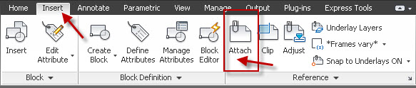
2. Then, in AutoCAD 2012, go to the Insert tab on the ribbon and select Attach on the Reference panel.

3. After clicking on Attach, you will see the following: –

4. Select your Facility Plan (FP) drawing and click on Open.
5. You will then see the Attach Reference File dialog box.

6. Make sure that you set the reference as an Attachment and that scale is set to 1 and your insertion point is X=0, Y=0 and Z=0. Ideally set its Path Type as Full. You can set it to Relative but make sure that the reference drawing is in the same folder as the current drawing otherwise AutoCAD will not find the reference drawing.
7. Click on OK and you will see your reference drawing (XREF). It looks grey because AutoCAD 2012 has a default setting to fade XREF drawings. If you cannot see your XREF, do a Zoom Extents (double-click the wheel on your mouse should do it).
8. Make sure you save your drawing at this point.
9. We now need to rename the XREF for layering purposes. Open up your Layer Properties Manager from the Home tab on the ribbon in the Layers panel.
10. You will see the following layers: –

11. XREFS is the layer the external reference drawing is on in the current drawing. The two layers actually in the XREF are preceded with the XREF drawing name.
12. To shorten this, we will rename the XREF drawing to rationalise the layer name listing.
13. Type RENAME and press Enter. Select Blocks as shown and you will see your XREF drawing in the list. Select your XREF drawing in the Items list.
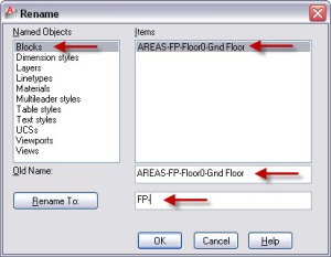
14. You will now see your original XREF drawing name as the Old Name. In the Rename To field, type in FP-. Click on the Rename To button. You will see the XREF block name change. Then click on OK.
NOTE: This does NOT change the actual XREF drawing name.
15. Open up the Layer Properties Manager again (see Step 9) and you will see that the layer names have updated accordingly.

Section 2 – Polyline your Floor and Room Areas.
Regardless of whether you are using the slickest, most expensive CAFM system or not, you will still need to polyline your floor and room areas. You MUST NOT use regular AutoCAD lines. They have to be polylined outlines.
There is a reason for this. Polylines carry what is known as xData, in this case, the area of the enclosed polyline (and also the perimeter, but we don’t actually need that).
If you open the Layer Properties Manager, you will see we already have a layer called ROOMAREAS.
1. Create a new layer called FLOORAREAS. Give it a green colour.
2. We now have two FM layers we can use. Make FLOORAREAS your current layer.

3. We can now cheat a little due to the simplicity of the exercise. Using the RECTANGLE command (which always creates a closed polyline), we can now trace the Floor Area using the inside wall edges. Just click on the diagonal corners shown using your Object Snaps.

4. You will end up with the Floor Area shown (which I have highlighted using lineweight for clarity).

5. Now, here’s the bit where you have to do some work! Repeat the polylining process from Step 1 but use ROOMAREAS as your current layer and polyline each Room Area as shown.

6. Make sure you save your drawing! J
OK, that is enough for today! Come back for Measuring Areas (AutoCAD) – Part 2 next week where we will look at ways to measure our floor and room areas.
If you do want the initial drawings to work with, just pop me an email at shaun.bryant@cadfmconsult.co.uk (They will be in AutoCAD 2010 DWG format).
Happy CADD’ing!
SB
Pingback: Terrific Tuesday #002 | AutoCAD Quick Tip – Measuring Areas – Part 4 – CADFMconsultants